Wednesday, July 1, 2015

Configuring OSPF Summarization

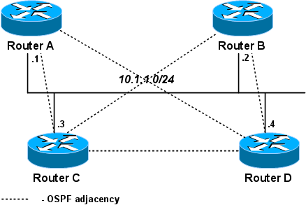
his scenario covers the same network topology shown in Figure 4-4. The aim of any network designer is to use summarization wherever possible. OSPF, as you have seen, has some advanced features to allow summarization. The first method you can apply is intra-area summarization on the backbone Routers R1 and R2. A total of 30 networks (contiguous) exist from 131.108.1.0 to 131.108.31.255.
For the core routers in area 0, namely R1, R2, R3, and R4, which pass on routing information to other core or remote routers, you need to have a more detailed view of the network. This detail is required so you do not perform any summarization on the core network and maintain a full IP routing topology in the core (or backbone) network.
The access-level routers, R5, R6, R7, and R8, do not typically require an IP routing entry for every network in the core because they require access to only the core network in area 0, the backbone. Therefore, these routers are perfect examples of how you can use summarization to reduce the size of routing tables. Only a single exit point to the core of the network exists, so you can configure stubby networks. First, use some summary commands. Example 4-18 displays R5's IP routing table.

Example 4-18. R5's Current IP Routing Table

R5#show ip route
Codes: C - connected, O - OSPF, IA - OSPF inter area
       N1 - OSPF NSSA external type 1, N2 - OSPF NSSA external type 2
       E1 - OSPF external type 1, E2 - OSPF external type 2, E - EGP
     131.108.0.0/16 is variably subnetted, 41 subnets, 2 masks
O IA    131.108.255.16/30 [110/983] via 131.108.255.9, 04:14:50, Serial0
O IA    131.108.255.20/30 [110/983] via 131.108.255.9, 04:14:50, Serial0
O IA    131.108.255.0/30 [110/128] via 131.108.255.9, 04:14:51, Serial0
O IA    131.108.255.4/30 [110/919] via 131.108.255.9, 04:14:51, Serial0
C       131.108.255.8/30 is directly connected, Serial0
O       131.108.255.12/30 [110/128] via 131.108.255.9, 04:14:51, Serial0
O IA    131.108.131.0/24 [110/993] via 131.108.255.9, 04:05:58, Serial0
O       131.108.130.0/24 [110/138] via 131.108.255.9, 04:14:51, Serial0
O IA    131.108.129.0/24 [110/993] via 131.108.255.9, 04:14:51, Serial0
C       131.108.128.0/24 is directly connected, Ethernet0
O IA    131.108.15.0/24 [110/129] via 131.108.255.9, 03:51:04, Serial0
O IA    131.108.14.0/24 [110/129] via 131.108.255.9, 03:51:04, Serial0
O IA    131.108.13.0/24 [110/129] via 131.108.255.9, 03:51:14, Serial0
O IA    131.108.12.0/24 [110/129] via 131.108.255.9, 03:51:14, Serial0
O IA    131.108.11.0/24 [110/129] via 131.108.255.9, 03:51:14, Serial0
O IA    131.108.10.0/24 [110/129] via 131.108.255.9, 03:51:14, Serial0
O IA    131.108.9.0/24 [110/129] via 131.108.255.9, 03:51:15, Serial0
O IA    131.108.8.0/24 [110/129] via 131.108.255.9, 03:51:25, Serial0
O IA    131.108.7.0/24 [110/129] via 131.108.255.9, 03:51:25, Serial0
O IA    131.108.6.0/24 [110/129] via 131.108.255.9, 03:51:25, Serial0
O IA    131.108.5.0/24 [110/129] via 131.108.255.9, 03:51:25, Serial0
O IA    131.108.4.0/24 [110/129] via 131.108.255.9, 03:51:25, Serial0
O IA    131.108.3.0/24 [110/129] via 131.108.255.9, 03:51:25, Serial0
O IA    131.108.2.0/24 [110/129] via 131.108.255.9, 03:51:35, Serial0
O IA    131.108.1.0/24 [110/138] via 131.108.255.9, 04:14:52, Serial0
O IA    131.108.31.0/24 [110/139] via 131.108.255.9, 04:14:52, Serial0
O IA    131.108.30.0/24 [110/139] via 131.108.255.9, 04:14:52, Serial0
O IA    131.108.29.0/24 [110/139] via 131.108.255.9, 04:14:52, Serial0
O IA    131.108.28.0/24 [110/139] via 131.108.255.9, 04:14:52, Serial0
O IA    131.108.27.0/24 [110/139] via 131.108.255.9, 04:14:52, Serial0
O IA    131.108.26.0/24 [110/139] via 131.108.255.9, 04:14:52, Serial0
O IA    131.108.25.0/24 [110/139] via 131.108.255.9, 04:14:53, Serial0
O IA    131.108.24.0/24 [110/139] via 131.108.255.9, 04:14:53, Serial0
O IA    131.108.23.0/24 [110/139] via 131.108.255.9, 04:14:53, Serial0
O IA    131.108.22.0/24 [110/139] via 131.108.255.9, 04:14:53, Serial0
O IA    131.108.21.0/24 [110/139] via 131.108.255.9, 04:14:53, Serial0
O IA    131.108.20.0/24 [110/139] via 131.108.255.9, 04:14:53, Serial0
O IA    131.108.19.0/24 [110/139] via 131.108.255.9, 04:14:53, Serial0
O IA    131.108.18.0/24 [110/139] via 131.108.255.9, 04:14:53, Serial0
O IA    131.108.17.0/24 [110/139] via 131.108.255.9, 04:14:53, Serial0
O IA    131.108.16.0/24 [110/139] via 131.108.255.9, 04:14:53, Serial0
O       131.108.36.0/24 [110/11] via 131.108.255.9, 04:14:53, Serial0
Use OSPF summarization for the core IP networks ranging from 131.108.1.0 to 131.108.31.255 on Routers R3 and R4. Example 4-19 displays the use of the IOS area area ID rang e mask command on R3.

Example 4-19. Summary on R3

R3(config)#router ospf 1
R3(config-router)#area 0 ?
  authentication  Enable authentication
  default-cost    Set the summary default-cost of a NSSA/stub area
  nssa            Specify a NSSA area
  range           Summarize routes matching address/mask (border routers only)
  stub            Specify a stub area
  virtual-link    Define a virtual link and its parameters
R3(config-router)#area 0 range 131.108.0.0 ?
  A.B.C.D  IP mask for address

R3(config-router)#area 0 range 131.108.0.0 255.255.224.0

The IOS tells you only ABRs can perform OSPF summarization. Routers R3 and R4 are ABRs; hence, you can perform network summarization on R3 and R4.
Example 4-20 displays the OSPF summary on R4.

Example 4-20. Summary on R4

R4(config)#router ospf 1
R4(config-router)#area 0 range 131.108.1.0 255.255.224.0

View the IP routing table on R5. Example 4-21 displays R5's routing table after network summarization is configured on R3 and R4. Also displayed in Example 4-21 are a few ping requests to IP networks covered in the summary range 131.108.0.0/19, which are networks covering the range 131.108.1.0 to 131.108.31.255.

Example 4-21. Summary on R5

R5#show ip route
Codes: C - connected, O - OSPF, IA - OSPF inter area
       N1 - OSPF NSSA external type 1, N2 - OSPF NSSA external type 2
       E1 - OSPF external type 1, E2 - OSPF external type 2
     131.108.0.0/16 is variably subnetted, 11 subnets, 3 masks
O IA    131.108.255.16/30 [110/983] via 131.108.255.9, 05:09:00, Serial0
O IA    131.108.255.20/30 [110/983] via 131.108.255.9, 05:09:00, Serial0
O IA    131.108.255.0/30 [110/128] via 131.108.255.9, 05:09:00, Serial0
O IA    131.108.255.4/30 [110/919] via 131.108.255.9, 05:09:00, Serial0
C       131.108.255.8/30 is directly connected, Serial0
O       131.108.255.12/30 [110/128] via 131.108.255.9, 05:09:00, Serial0
O       131.108.36.0/24 [110/11] via 131.108.255.9, 05:14:53, Serial0
O IA    131.108.131.0/24 [110/993] via 131.108.255.9, 05:00:08, Serial0
O       131.108.130.0/24 [110/138] via 131.108.255.9, 05:09:00, Serial0
O IA    131.108.129.0/24 [110/993] via 131.108.255.9, 05:09:01, Serial0
C       131.108.128.0/24 is directly connected, Ethernet0
O IA    131.108.0.0/19 [110/129] via 131.108.255.9, 00:46:25, Serial0
R5#ping 131.108.1.1

Type escape sequence to abort.
Sending 5, 100-byte ICMP Echos to 131.108.1.1, timeout is 2 seconds:
!!!!! (R1 Ethernet e0/0 address)
Success rate is 100 percent (5/5), round-trip min/avg/max = 32/32/32 ms
R5#ping 131.108.2.1
Type escape sequence to abort.
Sending 5, 100-byte ICMP Echos to 131.108.2.1, timeout is 2 seconds:
!!!!!
Success rate is 100 percent (5/5), round-trip min/avg/max = 28/31/32 ms
R5#ping 131.108.3.1
Type escape sequence to abort.
Sending 5, 100-byte ICMP Echos to 131.108.3.1, timeout is 2 seconds:
!!!!!
Success rate is 100 percent (5/5), round-trip min/avg/max = 32/32/32 ms
R5#ping 131.108.31.1
Type escape sequence to abort.
Sending 5, 100-byte ICMP Echos to 131.108.31.1, timeout is 2 seconds:
!!!!!
Success rate is 100 percent (5/5), round-trip min/avg/max = 32/32/36 ms
By using a simple command on the ABRs, you have significantly reduced the IP routing table size on R5 to nine remote OSPF entries. The same occurs on Routers R6, R7, and R8.
Also because R5 and R7 have single exit points to the core, you can configure a stub network. You cannot configure a stub network on R8 because you have a virtual link. To create a stub network, use the area area id stub command. Create a stub network between Routers R3 (the ABR) and R5. Example 4-22 displays the stub configuration on R3.

Example 4-22. Stub Configuration on R3

R3(config)#router ospf  1
R3(config-router)#area 10 stub

If you attempt to configure a stub network on R4, Cisco's IOS displays the message in Example 4-23.

Example 4-23. Configuring a Stub Area

R4(config)#router ospf 1
R4(config-router)#area 10 stub

   % OSPF: Area cannot be a stub as it contains a virtual link
R4(config-router)#
You cannot create a stub between R4 and R8 because of the virtual link. So, change the area assignments on R8 to area 10 so you can create a stub.
Figure 4-5 displays the change of area assignments to remove the necessity of a virtual link between R8 and R4. To change the area assignment on R8 from 11 to 10, configure the following commands on R8:
04fig05.gif
Figure 4-5 Sample Network After R8 Area Change
no network 131.108.131.0 0.0.0.255 area 11
network 131.108.131.0 0.0.0.255 area 10

Because a change has been made to OSPF area assignment, you must ensure that OSPF is still active on R5. Example 4-24 displays R5's OSPF neighbor state after you configure the ABR R3 as a stub network in area 10.

Example 4-24. show ip ospf neighbor Command on R5

R5#show ip ospf neighbor

Neighbor ID     Pri   State           Dead Time   Address         Interface
131.108.255.13    1   DOWN/  -           -        131.108.255.9   Serial0
The OSPF relationship between R3 and R5 is down because if one router is configured as a stub, the neighboring router must also be configured as a stub, and in this case, R5 has not yet been configured as a stub. Example 4-25 displays the configuration of a stub network on R5 and the OSPF relationship change to full adjacency.

Example 4-25. Stub Configuration on R5

R5(config)#router ospf 1
R5(config-router)#area 10 stub
R5#sh ip ospf neighbor

Neighbor ID     Pri   State           Dead Time   Address         Interface
131.108.255.13    1   FULL/  -        00:00:38    131.108.255.9   Serial0

Now, view the IP routing table on R5. Example 4-26 displays the new IP routing table after the stub configuration is completed on both Routers R3 and R5.

Example 4-26. R5's Routing Table

R5#sh ip route

   Gateway of last resort is 131.108.255.9 to network 0.0.0.0
     131.108.0.0/16 is variably subnetted, 10 subnets, 3 masks
O IA    131.108.255.16/30 [110/983] via 131.108.255.9, 00:01:22, Serial0
O IA    131.108.255.20/30 [110/983] via 131.108.255.9, 00:01:22, Serial0
O IA    131.108.255.0/30 [110/128] via 131.108.255.9, 00:01:22, Serial0
O IA    131.108.255.4/30 [110/919] via 131.108.255.9, 00:01:22, Serial0
C       131.108.255.8/30 is directly connected, Serial0
O       131.108.255.12/30 [110/128] via 131.108.255.9, 00:01:22, Serial0
O       131.108.36.0/24 [110/11] via 131.108.255.9, 00:01:22, Serial0
O       131.108.131.0/24 [110/128] via 131.108.255.9, 00:01:22, Serial0
O IA    131.108.131.0/24 [110/993] via 131.108.255.9, 00:01:22, Serial0
O IA    131.108.129.0/24 [110/993] via 131.108.255.9, 00:01:22, Serial0
C       131.108.128.0/24 is directly connected, Ethernet0
O IA    131.108.0.0/19 [110/129] via 131.108.255.9, 00:01:23, Serial0
O*IA 0.0.0.0/0 [110/65] via 131.108.255.9, 00:01:23, Serial0

You now have on R5 a default route labeled 0.0.0.0 through the next hop address 131.108.255.9 (R3). You have a gateway of last resort, which effectively means any packets to unknown destinations are sent to the next hop address 131.108.255.9 (R3). Configuring a stub network performs exactly this function; it provides a default route.
Now, you can assume that all IP traffic from the edge routers is destined for the core network, so there is no reason for R5 or R6 to have network entries for every individual IP route in the core. All IP traffic is destined for the core anyway. To further reduce the IP routing table, you can configure OSPF to stop the entries labeled as O IA (interarea routes) from populating the edge routers by configuring a stubby network with the no-summary option by applying the IOS area area id stub no-summary command.
This option prevents the ABR from sending summary link advertisements from other areas except the area that connects R5, area 10 in this case. To ensure OSPF full adjacency is achieved between R3, R4, R5, R6, R7, and R8, you must configure both the core and edge routers. Example 4-27 displays the configuration of the core router, R3, with the no-summary option.

Example 4-27. Preventing Summary LSAs from Other Areas

R3(config)#router ospf 1
R3(config-router)#area 10 stub no-summary

You also complete the area 10 stub no-summary on the remaining routers. Example 4-28 displays the no-summary option configured on R5.

Example 4-28. no-summary Command Option on R5

R5(config)#router ospf 1
R5(config-router)#area 10 stub no-summary

R5's routing table should now contain even fewer entries. Example 4-29 displays R5 IP routing table. View the IP routing table on R5 in Example 4-29 and compare it to Example 4-26.

Example 4-29. R5's IP Routing Table

R5#show ip route
Gateway of last resort is 131.108.255.9 to network 0.0.0.0
     131.108.0.0/16 is variably subnetted, 9 subnets, 2 masks
O       131.108.255.16/30 [110/138] via 131.108.255.9, 00:01:04, Serial0
O       131.108.255.20/30 [110/138] via 131.108.255.9, 00:01:04, Serial0
C       131.108.255.8/30 is directly connected, Serial0
O       131.108.255.12/30 [110/128] via 131.108.255.9, 00:01:04, Serial0
O       131.108.131.0/24 [110/148] via 131.108.255.9, 00:01:04, Serial0
O       131.108.130.0/24 [110/138] via 131.108.255.9, 00:01:04, Serial0
O       131.108.129.0/24 [110/148] via 131.108.255.9, 00:01:04, Serial0
C       131.108.128.0/24 is directly connected, Ethernet0
O       131.108.36.0/24 [110/74] via 131.108.255.9, 00:01:04, Serial0
O*IA 0.0.0.0/0 [110/65] via 131.108.255.9, 00:01:04, Serial0
The only networks displayed now are the default network and networks residing in the same area as Router R5, which is area 10. You now have only 8 remote entries instead of over 30, as shown in Example 4-18. The use of the stub configuration is effective in this type of network topology.
List the full OSPF working configurations of the ABR Routers R3 and R4 and the edge routers that are configured as stubby networks. Example 4-30 displays R3's OSPF configuration. The shaded portion highlights the configuration required for the stub network.

Example 4-30. R3's OSPF Working Configuration

router ospf 1
 network 131.108.255.0 0.0.0.3 area 0
 network 131.108.255.8 0.0.0.3 area 10
 network 131.108.255.12 0.0.0.3 area 10
 network 131.108.36.0 0.0.0.255 area 10
 area 0 range 131.108.0.0 255.255.224.0
 area 10 stub no-summary

Example 4-31 displays R4's full OSPF working configuration. The shaded portion highlights the configuration required for the stub network.

Example 4-31. R4's OSPF Working Configuration

router ospf 1
 area 0 range 131.108.0.0 255.255.224.0
 area 10 stub no-summary
 network 131.108.36.0 0.0.0.255 area 10
 network 131.108.255.4 0.0.0.3 area 0
 network 131.108.255.16 0.0.0.3 area 10
 network 131.108.255.20 0.0.0.3 area 10
Example 4-32 displays R5's OSPF working configuration. The shaded portion highlights the configuration required for the stub network.

Example 4-32. R5's OSPF Working Configuration

router ospf 1
 area 10 stub no-summary
 network 131.108.128.0 0.0.0.255 area 10
 network 131.108.255.4 0.0.0.3 area 10
!
Example 4-33 displays R6's OSPF working configuration. The shaded portion highlights the configuration required for the stub network.

Example 4-33. R6's OSPF Working Configuration

router ospf 1
 area 10 stub no-summary
 network 131.108.129.0 0.0.0.255 area 10
 network 131.108.255.8 0.0.0.3 area 10
Example 4-34 displays R7's OSPF working configuration. The shaded portion highlights the configuration required for the stub network.

Example 4-34. R7's OSPF Working Configuration

router ospf 1
 area 10 stub no-summary
 network 131.108.130.0 0.0.0.255 area 10
 network 131.108.255.12 0.0.0.3 area 10
Example 4-35 displays R8's OSPF working configuration. The shaded portion highlights the configuration required for the stub network.

Example 4-35. R8's OSPF Working Configuration

router ospf 1
 area 10 stub no-summary
 network 131.108.131.0 0.0.0.255 area 10
 network 131.108.255.20 0.0.0.3 area 10

Practical Exercise: OSPF and RIP Redistribution

Configure the network in Figure 4-8 for OSPF between the three routers named SanFran, Mel, and Simon. Configure the edge router named Sydney for RIP and ensure IP connectivity among all four routers. You must use only RIPv1 and OSPF as your IP routing protocols. Ensure that a default route appears on all routers so users can connect to the Internet. Configure summarization wherever possible to minimize IP routing tables.
04fig08.gif
Figure 4-8 -to- Redistribution

Practical Exercise Solution

The router named Simon is configured in the OSPF area 0 (backbone) and the RIP domain and needs to run redistribution between OSPF and OSPF. Also, because you are using RIPv1, you must also provide summary addresses for all networks, but not /24 because RIPv1 does not carry subnet mask information in routing updates. (RIPv2 does).
Router SanFran is connected to the Internet, so you need to configure SanFran to provide a default route to the rest of the internal network by using the OSPF command default-information originate always. This IOS command injects a default route into the OSPF domain and Router Simon because redistribution also injects a default route into the RIP domain.
The following are the full working configurations of all four routers with the shaded portions highlighting critical configuration commands. Example 4-60 displays the full working configuration of Router Sydney. Sydney is running RIP only.

Example 4-60. Full Working Configuration of Router Sydney

hostname Sydney
!
logging buffered 64000 debugging
enable password cisco
!
ip subnet-zero
no ip domain-lookup
interface Ethernet0/0
 ip address 141.108.1.1 255.255.255.0
 no ip directed-broadcast
!
interface Serial0/0
 shutdown
!
interface Serial0/1
 shutdown
!
router rip
 network 141.108.0.0
!
line con 0
line aux 0
line vty 0 4
!
end
Example 4-61 displays the full working configuration of Router Simon. Simon is running OSPF and RIP. You must always be careful when redistributing information from one routing domain into another. Simon advertises the non /24 subnets as Class C networks so the RIP domain (Sydney router) can inject them into the routing table. Because RIPv1 is classless and the subnet 141.108.1.0/24 is configured locally, all interfaces in this Class B network (141.108.0.0) are assumed to be Class C.

Example 4-61. Full Working Configuration of Router Simon

Building configuration...

Current configuration:
!
version 12.0
service timestamps debug uptime
service timestamps log uptime
no service password-encryption
!
hostname Simon
!
enable password cisco
!
ip subnet-zero
no ip domain-lookup
!
cns event-service server
!
interface Ethernet0
 ip address 141.108.2.1 255.255.255.128
!
interface Ethernet1
 ip address 141.108.1.4 255.255.255.0
!
interface Serial0
 shutdown
!
interface Serial1
 shutdown
!
interface Serial2
 ip address 141.108.255.5 255.255.255.252
 clockrate  128000
!
interface Serial3
 ip address 141.108.255.1 255.255.255.252
 clockrate  128000
!
router ospf 1
 summary-address 141.108.2.0 255.255.255.0
 summary-address 141.108.255.0 255.255.255.0
 summary-address 141.108.3.0 255.255.255.0
 summary-address 141.108.4.0 255.255.255.0
 redistribute connected subnets
 redistribute rip metric 10 subnets
 network 141.108.2.0 0.0.0.127 area 0
 network 141.108.255.0 0.0.0.255 area 0
!
router rip
 redistribute ospf 1 metric 2
 passive-interface Ethernet0 -> Stops RIP updates on OSPF interfaces
 passive-interface Serial2
 passive-interface Serial3
 network 141.108.0.0
!
=
ip route 141.108.3.0 255.255.255.0 Null0
ip route 141.108.4.0 255.255.255.0 Null0
!
line con 0
line aux 0
line vty 0 4
!
end
Example 4-62 displays the full working configuration of Router Mel. Mel is running OSPF only.

Example 4-62. Full Working Configuration of Router Mel

hostname Mel
enable password cisco
!
ip subnet-zero
no ip domain-lookup
!
interface Ethernet0
 ip address 141.108.3.1 255.255.255.248
!
interface Serial0
 ip address 141.108.255.6 255.255.255.252
!
interface Serial1
 shutdown
!
router ospf 1
network 141.108.0.0 0.0.255.255 area 0
!
line con 0
line 1 8
line aux 0
line vty 0 4
!
end
Example 4-63 displays the full working configuration of Router SanFran. SanFran has a default static route pointing to Serial 1, which is the Internet connection. Under the routing OSPF process, this default route is injected by using the default-information originate always command.

Example 4-63. Full Working Configuration of Router SanFran

hostname SanFran
!
no ip domain-lookup
!
interface Ethernet0
 ip address 141.108.4.1 255.255.255.240
!
interface Serial0
 ip address 141.108.255.2 255.255.255.252
!
interface Serial1
 shutdown
!
router ospf 1
 network 141.108.0.0 0.0.255.255 area 0
 default-information originate always
!
ip route 0.0.0.0 0.0.0.0 Serial1
!
line con 0
line aux 0
line vty 0 4
!
end

Simple OSPF examples

Simple OSPF configuration

The following example illustrates how to configure single-area OSPF network. Let’s assume we have the following network.
Image6005.gif
Example network consists of 3 routers connected together within 10.10.1.0/24 network and each router has also one additional attached network.
In this example following IP addresses are configured:
 [admin@MikroTikR1]/ip address add address=10.10.1.1/30 interface=ether1
 [admin@MikroTikR1]/ip address add address=10.10.1.5/30 interface=ether2
 [admin@MikroTikR1]/ip address add address=210.13.1.0/28 interface=ether3
 [admin@MikroTikR2]/ip address add address=10.10.1.6/30 interface=ether1
 [admin@MikroTikR2]/ip address add address=10.10.1.9/30 interface=ether2
 [admin@MikroTikR2]/ip address add address=172.16.1.0/16 interface=ether3
 [admin@MikroTikR3]/ip address add address=10.10.1.2 /30 interface=ether1
 [admin@MikroTikR3]/ip address add address=10.10.1.10/30 interface=ether2
 [admin@MikroTikR3]/ip address add address=192.168.1.0/24 interface=ether3

There are three basic elements of OSPF configuration:
  • Enable OSPF instance
  • OSPF area configuration
  • OSPF network configuration
General information is configured in /routing ospf instance menu. For advanced OSPF setups, it is possible to run multiple OSPF instances. Default instance configuration is good to start, we just need to enable default instance.
R1:
[admin@MikroTikR1] /routing ospf instance> add name=default
R2:
[admin@MikroTikR2] /routing ospf instance> add name=default

R3:
[admin@MikroTikR3] /routing ospf instance> add name=default

Show OSPF instance information:
[admin@MikroTikR1] /routing ospf instance> print 
Flags: X - disabled 
 0   name="default" router-id=0.0.0.0 distribute-default=never 
     redistribute-connected=as-type-1 redistribute-static=as-type-1 
     redistribute-rip=no redistribute-bgp=no redistribute-other-ospf=no 
     metric-default=1 metric-connected=20 metric-static=20 metric-rip=20 
     metric-bgp=auto metric-other-ospf=auto in-filter=ospf-in 
out-filter=ospf-out

As you can see router-id is 0.0.0.0, it means that router will use one of router's IP addresses as router-id. In most cases it is recommended to set up loopback IP address as router-id. Loopback IP address is virtual, software address that is used for router identification in network. The benefits are that loopback address is always up (active) and can’t be down as physical interface. OSPF protocol used it for communication among routers that identified by router-id. Loopback interface are configured as follows:
Create bridge interface named, for example, “loopback”:
[admin@MikroTikR1] /interface bridge> add name=loopback
Add IP address:
[admin@MikroTikR1] > ip address add address=10.255.255.1/32 interface=loopback 
Configure router-id as loopback:
[admin@MikroTikR1] /routing ospf instance> set 0 router-id=10.255.255.1
This can be done on other routers (R2, R3) as well.
Next step is to configure OSPF area. Backbone area is created during RouterOS installation and additional configuration is not required.
Icon-note.png
Note: Remember that backbone area-id is always (zero) 0.0.0.0.
And the last step is to add network to the certain OSPF area.
On R1
[admin@MikroTikR1] /routing ospf network> add network=210.13.1.0/28 area=backbone
[admin@MikroTikR1] /routing ospf network> add network=10.10.1.0/30 area=backbone
[admin@MikroTikR1] /routing ospf network> add network=10.10.1.4/30 area=backbone
Instead of typing in each network, you can aggregate networks using appropriate subnet mask. For example, to aggregate 10.10.1.0/30, 10.10.1.4/30, 10.10.1.8/30 networks, you can set up following ospf network:
[admin@MikroTikR1] /routing ospf network> add network=10.10.1.0/'''24''' area=backbone

R2:
[admin@MikroTikR2] /routing ospf network> add network=172.16.1.0/16 area=backbone
[admin@MikroTikR2] /routing ospf network> add network=10.10.1.0/24 area=backbone
R3:
[admin@MikroTikR3] /routing ospf network> add network=192.168.1.0/24 area=backbone
[admin@MikroTikR3] /routing ospf network> add network=10.10.1.0/24 area=backbone

You can verify your OSPF operation as follows:
  • Look at the OSPF interface menu to verify that dynamic entry was created:
[admin@MikroTikR1] /routing ospf interface> print
  • Check your OSPF neighbors, what DR and BDR is elected and adjacencies established:
[admin@MikroTikR1] /routing ospf neighbor> print
  • Check router’s routing table (make sure OSPF routes are present):
[admin@MikroTik_CE1] > ip route print

Simple multi-area configuration

Backbone area is the core of all OSPF network, all areas have to be connected to the backbone area. Start configuring OSPF from backbone and then expand network configuration to other areas.
Image6006.gif

Lets assume that IP addresses are already configured and default OSPF instance is enabled.
All we need to do is:
  • create an area
  • attach OSPF networks to the area

R1 configuration:
/routing ospf> add name=area1 area-id=0.0.0.1
/routing ospf> add network=10.0.1.0/24 area=backbone
/routing ospf> add network=10.1.1.0/30 area=area1
R2 configuration:
/routing ospf> add name=area2 area-id=0.0.0.2
/routing ospf> add network=10.0.1.0/24 area=backbone
/routing ospf> add network=10.1.2.0/30 area=area2
R3 configuration:
/routing ospf> add name=area1 area-id=0.0.0.1
/routing ospf> add network=10.1.1.0/30 area=area1
R4 configuration:
/routing ospf> add name=area2 area-id=0.0.0.2
/routing ospf> add network=10.1.2.0/30 area=area2

Now you can check routing table using command /ip route print
Routing table on router R3:
[admin@R3] > ip route print 
Flags: X - disabled, A - active, D - dynamic, 
C - connect, S - static, r - rip, b - bgp, o - ospf, m - mme, 
B - blackhole, U - unreachable, P - prohibit 
 #      DST-ADDRESS        PREF-SRC        GATEWAY            DISTANCE
 1 ADo  10.0.1.0/24                        10.1.1.1           110
 2 ADC  10.1.1.0/30         10.1.1.2       ether1             110     
 3 ADo  10.1.2.0/30                        10.1.1.1           110        
 4 ADC  192.168.1.0/24      192.168.1.1    ether2             0       
As you can see remote networks 172.16.0.0/16 and 192.168.2.0/24 are not in the routing table, because they are not distributed by OSPF. Redistribution feature allows different routing protocols to exchange routing information making possible, for example, to redistribute static or connected routes into OSPF. In our setup we need to redistribute connected network. We need to add following configuration on routers R1, R2 and R3.
[admin@R3] /routing ospf instance> set 0 redistribute-connected=as-type-1 
[admin@R3] /routing ospf instance> print 
Flags: X - disabled 
 0   name="default" router-id=0.0.0.0 distribute-default=never 
     <u>redistribute-connected=as-type-1</u> redistribute-static=no 
     redistribute-rip=no redistribute-bgp=no redistribute-other-ospf=no 
     metric-default=1 metric-connected=20 metric-static=20 metric-rip=20 
     metric-bgp=auto metric-other-ospf=auto in-filter=ospf-in 
     out-filter=ospf-out

Now check router R3 to see if routes 192.168.2.0/24 and 172.16.0.0/16 are installed in routing table.
[admin@R3] > ip route print 
Flags: X - disabled, A - active, D - dynamic, 
C - connect, S - static, r - rip, b - bgp, o - ospf, m - mme, 
B - blackhole, U - unreachable, P - prohibit 
 #      DST-ADDRESS        PREF-SRC        GATEWAY            DISTANCE
 1 ADo  10.0.1.0/24                        10.1.1.1           110
 2 ADC  10.1.1.0/30         10.1.1.2       ether1             110     
 3 ADo  10.1.2.0/30                        10.1.1.1           110
 4 ADo  172.16.0.0/16                      10.1.1.1           110       
 5 ADC  192.168.1.0/24      192.168.1.1    ether2             0 
 6 ADo  192.168.2.0/24                     10.1.1.1           110      

NBMA networks

OSPF network type NBMA (Non-Broadcast Multiple Access) uses only unicast communications, so it is the preferred way of OSPF configuration in situations where multicast addressing is not possible or desirable for some reasons. Examples of such situations:
  • in 802.11 wireless networks multicast packets are not always reliably delivered (read Multicast_and_Wireless for details); using multicast here can create OSPF stability problems;
  • using multicast may be not efficient in bridged or meshed networks (i.e. large layer-2 broadcast domains).
Especially efficient way to configure OSPF is to allow only a few routers on a link to become the designated router. (But be careful - if all routers that are capable of becoming the designated router will be down on some link, OSPF will be down on that link too!) Since a router can become the DR only when priority on it's interface is not zero, this priority can be configured as zero in interface and nbma-neighbor configuration to prevent that from happening.
Ospf-nbma.png
In this setup only C and D are allowed to become designated routers.
On all routers:
routing ospf network add network=10.1.1.0/24 area=backbone
routing ospf nbma-neighbor add address=10.1.1.1 priority=0
routing ospf nbma-neighbor add address=10.1.1.2 priority=0
routing ospf nbma-neighbor add address=10.1.1.3 priority=1
routing ospf nbma-neighbor add address=10.1.1.4 priority=1
(For simplicity, to keep configuration the same on all routers, nbma-neighbor to self is also added. Normally you wouldn't do that, but it does not cause any harm either.)
Configure interface priorities. On routers A, B:
routing ospf interface add interface=ether1 network-type=nbma priority=0
On routers C, D (they can become the designated router):
routing ospf interface add interface=ether1 network-type=nbma priority=1

Results

On Router A:
[admin@A] > routing ospf neighbor print
 0 router-id=10.1.1.5 address=10.1.1.5 interface=ether1 priority=1 dr-address=10.1.1.4
   backup-dr-address=10.1.1.3 state="Full" state-changes=6 ls-retransmits=0
   ls-requests=0 db-summaries=0 adjacency=4m53s

 1 router-id=10.1.1.3 address=10.1.1.3 interface=ether1 priority=1 dr-address=1.1.1.4
   backup-dr-address=10.1.1.3 state="Full" state-changes=6 ls-retransmits=0
   ls-requests=0 db-summaries=0 adjacency=4m43s

 2 address=10.1.1.2 interface=ether1 priority=0 state="Down" state-changes=2

 3 address=10.1.1.1 interface=ether1 priority=0 state="Down" state-changes=2
On Router D:
[admin@D] > routing ospf neighbor print
 0 address=10.1.1.4 interface=ether1 priority=1 state="Down" state-changes=2

 1 router-id=10.1.1.3 address=10.1.1.3 interface=ether1 priority=1 dr-address=10.1.1.4
   backup-dr-address=10.1.1.3 state="Full" state-changes=6 ls-retransmits=0
   ls-requests=0 db-summaries=0 adjacency=6m8s

 2 router-id=10.1.1.2 address=10.1.1.2 interface=ether1 priority=0 dr-address=10.1.1.4
   backup-dr-address=10.1.1.3 state="Full" state-changes=5 ls-retransmits=0
   ls-requests=0 db-summaries=0 adjacency=6m4s

 3 router-id=10.1.1.1 address=10.1.1.1 interface=ether1 priority=0 dr-address=10.1.1.4
   backup-dr-address=10.1.1.3 state="Full" state-changes=5 ls-retransmits=0
   ls-requests=0 db-summaries=0 adjacency=6m4s

OSPF Forwarding Address

OSPF may take extra hops at the boundary between OSPF routing domain and another Autonomous System. By looking at the following illustration you can see that even if router R3 is directly connected, packets will travel through the OSPF network and use router R1 as a gateway to other AS.
To overcome this problem, concept of OSPF forwarding-address was introduced. This concept allows to say "Send traffic directly to router R1". This is achieved by setting forwarding address other than itself in LSA updates indicating that there is an alternate next-hop. Mostly all the time forwarding address is left 0.0.0.0, suggesting that the route is reachable only through the advertising router.

Ospf-forwarding.png
Lets assume that router R1 has static route to external network 192.168.0.0/24. OSPF is running between R1,R2 and R3 and static route is distributed across the OSPF network.
The problem in such setup is obvious, R2 can not reach external network directly. Traffic from R2 will be forwarded to routerR1
Ospf-forwarding-traffic.png
[admin@R2] /ip route> print 
Flags: X - disabled, A - active, D - dynamic, 
C - connect, S - static, r - rip, b - bgp, o - ospf, m - mme, 
B - blackhole, U - unreachable, P - prohibit 
 #      DST-ADDRESS        PREF-SRC        GATEWAY            DISTANCE
...   
 8 ADo  192.168.0.0/24                       10.1.101.10          110

Fortunately OSPF has mechanism to solve such situations. OSPF router can set forwarding-address to something other than itself which indicates that alternate nexthop is possible. Mostly forwarding address is set to 0.0.0.0 suggesting that the route is reachable only via the advertising router.
Forwarding address is set in LSA, if following conditions are met:
  • OSPF must be enabled on next-hop interface
  • Interface is not passive
  • Interface is not p2p or p2mp
  • Next-hop address falls into network provided in ospf networks
So knowing conditions, we can make router R1 to set forwarding address. We simply need to add 10.1.101.0/24 network to OSPF networks in router's R1 configuration:
/routing ospf network add network=10.1.101.0/24 area=backbone
Icon-note.png
Note: OSPF adjacency between routers in 10.1.101.0/24 network is not required

Now lets verify that forwarding address is actually working:
[admin@R2] /ip route> print 
Flags: X - disabled, A - active, D - dynamic, 
C - connect, S - static, r - rip, b - bgp, o - ospf, m - mme, 
B - blackhole, U - unreachable, P - prohibit 
 #      DST-ADDRESS        PREF-SRC        GATEWAY            DISTANCE
...   
 8 ADo  192.168.0.0/24                       10.1.101.1          110
On all OSPF routers you will see LSA set with forwarding address other than 0.0.0.0
[admin@R2] /routing ospf lsa>print detail
 instance=default area=external type=as-external id=192.168.0.0 
   originator=10.1.101.1 sequence-number=0x80000073 age=16 checksum=0x8510 
   options="E" body=
     netmask=255.255.255.0
     forwarding-address=10.1.101.1
     metric=30
     route-tag=0x0
     type1

OSPF and EIGRP Concepts and Configuration

Things to Remember about Link State Routing
  • Link state protocols advertise a large amount of topological information about the network (tells what every metric is for every link in the network)
  • Routers must calculate the metric (using Shortest path First Algorithm)
  • Routers perform CPU intensive computations on the data.
  • Discover neighbors before exchanging information.
Process of Learning Routes:
1. Each router discovers its neighbors on each interface, list kept in neighbors table.

2. Each router uses a reliable protocol to exchange topology information in its topology database.

3. Each router places the learned topology information in its topology database.

4. Each router then runs the SPF algorithm against its own topology database to calculate the best routes to each subnet in the database.

5. Each router finally places the best route to each subnet in the IP routing table.

OSPF Topology Database: Consists of lists of subnet numbers (links), list of routers (and links they are connected to).
-> Uniquely identifier each router in this database using OSPF Router ID (RID)
To select the RID
  • The router first checks for any loopback interfaces that are up, and chooses the highest numeric IP address of those.
  • If no loopback exists, router chooses highest IP address from interfaces that are up and up.
*Note: loopback interface is a virtual interface, configured with
interface loopback [interface #]
Each Router chooses RID when OSPY is initialized (during initial loading of IOS). If other interfaces come up after this, not used unless clear ip ospf process is issued.

Meeting OSPF Neighbors: Once router has assigned itself a RID, and some of its interfaces are up, the router is ready to meet its neighbors (connected routers).
  • Can become neighbors if connected to same subnet
  • Router multicasts OSPF Hello packets out each interface
  • Hello message follows IP packet header (port = 89)
  • Hello packets sent to 224.0.0.5 (all OSPF speaking routers)
  • Routers learn several things from Hello Packets:
  • RID, Area ID, Hello Interval, Dead Interval, router priority, designated router, backup designated router, and a list of neighbors sending router already knew about.
  • To confirm that a Hello Packet was received, next Hello Message will include the sender’s RID within the list of neighbors.
-> Once router sees its RID included, two-way state achieved, and more detailed information can be exchanged.
The following must match before routers become neighbors:
1. Subnet mask
2. Hello Interval
3. OSPF Area ID
4. Dead Interval
5. Subnet number (derived using the mask applied to the IP)

Reducing Overhead Using Designated Routers

Sometimes Designated Routers (DR) are required before sending Database Description (DD) packets.
  • DR’s always required on a LAN
  • Sometimes required with Frame Relay/ATM (depending on topology/config)
After DR is elected, all updates flow through the Designated Router (DR). This means that the DR collects and distributes the routing updates to alleviate OSPF update congestion.
Router decides if it needs to elect a DR depending on the network type.
Point-to-point DOES NOT need a DR
Broadcast (for LANs), always needs a DR
  • Non-broadcast Multiaccess (NBMA), for frame relay, sometimes needs DR, sometimes doesn’t. Has 5 different variations, configured with ip ospf network [type] command

** Since DR’s are so important, loss of one could cause delay in convergence, so Backup DR (BDR) is also needed. **
Electing The Designated Router
 
 
To elect, neighboring routers hold an election, and look at two fields in the Hello Packet:
* Router that sends the highest OSPF priority becomes DR
* If there is a tie, the highest RID wins.
 
To elect BDR, typically the second highest priority is used. *
 
Other Notes:
* Priority setting of 0 means router will never be DR
* Range of valid priority values is 1-255 (to become a DR)
* If DR is elected, then another router comes online with a higher priority, this router will not become DR until both the DR and BDR fail.
 

Once DR/BDR is elected:
1. Non-DR send updates to 224.0.0.6 (All OSPF DRs)
2. DR relays these messages to 224.0.0.5 (BDR does not forward, only receives)
3. Once router has exchanged its entire link state database, transition to Full State
Steady-State Operation: If Hello Interval is not received for [dead interval] amount of time, the router believes the neighbor has failed.
  • Default dead timer is 4 times the hello interval
(10 second hello, 40 second dead timer)
  • Router marks as "down" in its neighbor table
  • Runs the dijkstra algorithm to calculate new routes, floods to inform other routers of failed link
Loop Avoidance: Link state does not use SPF algorithm, but rather it relies on router broadcasting downed link immediately. This is the main reason for fast convergence time (distance vector uses hold time, split horizon, etc, while link state does not).

Scaling OSPF: If network has many routers (~50 or more, a few hundred subnets), would result in:
* Slow convergence time
* Memory shortages/processor overloading

Scalability Solutions Include:
OSPF Areas: Break up the network so that routers in one area know less topology information about the subnets in the other area, and don’t know about other routers at all.
Border Router: OSPF Area Border Router (ABR), border between 2 different areas (sits in both areas).
Makes other routers in same area view network as if it had fewer routers.
Area 0 defined as backbone, OSPF designs hierarchical

** Note: doesn’t change of subnets know, just decrease of bytes/require memory to process updates **

Summary of Distance Vector and Link State
FeatureLink StateDistance Vector
Convergence TimeFastSlow (loop avoidance features)
Loop avoidanceBuilt into protocolExtra features such as route poisoning, split horizon
Memory/CPUCan be large; good design can minimizeLow
Requires design effort for large networksYesNo
Public/Proprietary?OSPF = publicRIP = public
IGRP = Cisco proprietary

Balanced Hybrid Routing Protocol/EIGRP Concepts
EIGRP has some features that act like distance vector protocols, and some that act like link-state protocols.

Feature Comparison with IGRP:
SimilaritiesDifferences
Both Cisco proprietaryEIGRP converges faster
Same logic for equal-cost pathsEIGRP sends routing info once to neighbor, then again only when update occurs.

IGRP sends every 90 seconds.
Metric’s identical (EIGRP just scales by multiplying by 256)EIGRP can exchange for Novel IPX and AppleTalk, as well as IP

EIGRP Processes and Tables: Follows three general steps to be able to add routes to routing table:
1. EIGRP neighbor table: Routers discover other EIGRP routers that are attached to same subnet, form a neighbor relationship and keep a list in this table.
a. show ip eigrp neighbor
2. EIGRP topology table: Exchange of network topology information with known neighbors.
a. show ip eigrp topology
3. IP routing table: EIGRP analyzes topology information, puts lowest metric routes in this table.
a. show ip route -or- show ip route eigrp

** EIGRP could have up to 9 tables, since it supports IP, IPX, and AppleTalk **
Hello Messages: Used to perform neighbor discovery, continually sent to notice when connectivity has failed.
Interval determines how frequently it is sent
  • LANs/Point-to-point connections = 5 seconds
  • Multipoint WANS like Frame Relay = 60 seconds
Update Messages: Conveys topology information to neighbors.
  • Sent out multicast address 224.0.0.10 if updating multiple routers
  • Sent out Unicast address if single router updated
  • Reliable messages sent out Reliable Transport Protocol (RTP)
Updating the Routing Table while Avoiding Loops

EIGRP keeps basic topological information (but not full information)
  • Routes with feasible successor can be used immediately after route fails
  • Routes without on require EIGRP to perform Query and Response process to confirm that no loop exists.
Successors are in topology table, and are the best route (the route with lowest metric, which is also in routing table).

Feasible Successors are in topology table, and are placed when the neighbor has a lower metric for its route.
Diffusing Update Algorithm (DUAL) is used in query and reply process, when both successor and feasible successor fail. Sends query to confirm route exists, reply verifies route.

EIGRP Compared
FeatureEIGRPIGRPOSPF
Discovers neighbors before exchanging routing informationYNY
Builds topology table in addition to routing tableYNY
Converges QuicklyYNY
Bandwidth/delay metricYYN
Sends full routing table during updateNYN
Requires distance vector loop avoidance featuresNYN
Public StandardNNY
Uses DUAL AlgorithmYNN

IP Configuration Commands
CommandConfiguration Mode
router ospf process-idGlobal
network [ip address][wildcard mask] area[area id]Router subcommand
ip ospf cost interface costSets cost associated with interface
bandwidth [bandwidth]Sets interface bandwidth
auto-cost reference bandwidth [number]Router subcommand that sets the numerator in formula to calculate cost.
ip ospf hello [number]Interface subcommand that sets Hello interval, and sets dead interval to 4 times this number.
ip ospf network [type]Interface subcommand that defines the OSPF network type.

IP OSPF Exec Commands
CommandDescription
show ip route [ip address]Shows entire routing table, or subset if parameters entered.
show ip protocolsShows routing protocol parameters and current timer values.
show ip ospf interfaceList the area in which the router resides, and adjacent neighbors.
show ip ospf neighborLists neighbors and current status with neighbors, per interface.
show ip route ospfLists routes in routing table learned by ospf.
debug ip ospf eventsIssues log messages for each OSPF packet.
debug ip ospf packetIssues log messages describing the contents of all OSPF packets.
debug ip ospf helloIssues log messages describing Hellos and Hello failures.
OSPF Single-Area Configuration

interface Ethernet 0/0
ip address 10.1.1.1 255.255.255.0
interface serial 0/0
ip address 10.1.4.1 255.255.255.0

router ospf 1
network 10.0.0.0 0.255.255.255 area 0


Network : What interfaces you want to include in OSPF configuration . Here 10.0.0.0
Wildcard Mask: If bit set to 1, "don’t care" bit (and 0 = include) . Here 0.255.255.255
Area : What area this router is in. Here area 0

OSPF Configuration with Multiple Areas

If router has interfaces in multiple areas:

router ospf 1
network 10.1.1.1 0.0.0.0 area 0
network 10.1.4.1 0.0.0.0 area 1
network 10.1.6.1 0.0.0.0 area 0

Useful Commands
show ip ospf interface ->Details IP address, area , Router ID, Hello/Dead Interval, etc. for all interfaces

show ip route -> Shows all routes known by the router (C – Connected, O – OSPF)

show ip ospf neighbor -> Shows the routers ospf neighbors

Remember that the RID is that router’s highest IP address on a physical interface when OSPF starts running. Alternatively, if a loopback interface has been configured, OSPF uses the highest IP address on a loopback interface for the RID, even if that IP address is lower than some physical interface’s IP address.
OSPF Troubleshooting
Mismatched Hello Intervals:

* View neighbors:
show ip ospf neighbor ->Output doesn’t show neighbors

* Run debugging:
debug ip ospf hello -> Output shows mismatched Hello interval

* To identify the interface:
show ip ospf interface [interface] -> Will give you the hello interval

* To change hello interval for that interface:
configure terminal
interface [interface]
ip ospf hello [count]
exit
EIGRP Configuration
Configured exactly like IGRP, just switch "igrp" with "eigrp" in commands.
IP EIGRP Exec Commands
CommandDescription
show ip route [ip address]Shows entire routing table.
show ip eigrp neighborsLists EIGRP neighbors and status.
show ip eigrp topologyLists RIGRP topology table, including feasible successors/successors.
show ip route eigrpLists only EIGRP-learned routes
show ip eigrp trafficLists traffic statistics about EIGRP

Other Key Points
  • Letter "D" signifies EIGRP-learned routes
  • All routers must be in same AS number (network x.x.x.x [AS number])

IGRP to EIGRP Migration
Feature of EIGRP called Automatic Redistribution
image:Igrp-egrp.GIF
  • Border router must be configured for both IGRP and EIGRP
  • Both must use same AS number